|
by Peter Lankshear, Dunedin, New Zealand.
 'from someone who was there' as first published in NZVRS
Bulletin.
See
Electronics Australia October 1989 for Peter's other Hiker's Article 'from someone who was there' as first published in NZVRS
Bulletin.
See
Electronics Australia October 1989 for Peter's other Hiker's Article
Return to Hikers Main Page
Many consider that the “Baby Boomer” generation has been very
privileged but life for their parents, the “Depression Kids “, provided
far fewer material benefits. They grew up in a country still recovering
from the privations of the Depression and then in 1939 War with all its
problems was declared.
One outcome was that there were few luxuries and people had to be self
reliant. It was a case of “do it yourself” or go without. This was
especially true of the growing interest in radio. Other than the cinema,
there was not much other entertainment and radio filled the place today
occupied by television. Receivers were, however, expensive. According to
my rough calculations of 1939 prices converted to decimal, and based on
a loaf of bread, (2.5cents), postage of a letter (0.8cents) and a week’s
newspapers (10cents), money was worth about 50 times what it is now. A
typical wage was $10 a week. A small Collier and Beale basic 5 valve
Ensign mantel receiver cost $35 or in modern money, $1,750! No wonder
that kitset building was popular.
Home building had another attraction. There is a degree of satisfaction
in creating something that actually goes, and a working radio provided
continuing pleasure and utility, as well as a saving in cost.
A significant section of the home building fraternity comprised
technically inclined youngsters of the type who today would be burrowing
into computers. Of course, it was rarely that elaborate radios could be
afforded, but Hobby magazines regularly published circuits and
instructions for building modest receivers, each with some special
features to tempt the dismantling of last month’s wonder in favor of
something new.
Radio Shops
 Each major city had radio shops catering for the enthusiast and many of
these published catalogues, especially for out of town mail order
shoppers. Most of the contents of these well-thumbed pages could only be
dreamed about, but by saving pocket money, Christmas and birthday
presents and working at jobs, enough could be assembled to buy
essentials. To swell his bank account, the writer delivered newspapers.
This entailed leaving home at 4.45am in all weathers, biking into town
to pick up about 75 papers and then delivering them before 7.30am. Each
weekday this distance covered was about 15km and on Saturday mornings
there was an additional round collecting the shilling (10cents) from
each subscriber. My weekly reward for this was 11/- ($1.10) which was
about the cost of a typical valve. Each major city had radio shops catering for the enthusiast and many of
these published catalogues, especially for out of town mail order
shoppers. Most of the contents of these well-thumbed pages could only be
dreamed about, but by saving pocket money, Christmas and birthday
presents and working at jobs, enough could be assembled to buy
essentials. To swell his bank account, the writer delivered newspapers.
This entailed leaving home at 4.45am in all weathers, biking into town
to pick up about 75 papers and then delivering them before 7.30am. Each
weekday this distance covered was about 15km and on Saturday mornings
there was an additional round collecting the shilling (10cents) from
each subscriber. My weekly reward for this was 11/- ($1.10) which was
about the cost of a typical valve.
Foremost in the kitset business was the Dick Smith of the time, the
Electric Lamphouse of 11 Manners St. Wellington. Run by an astute
businessman by the name of Cornish, the Lamphouse published its Annual,
a catalogue of all manner of radio goodies as well as circuits and
useful data. As well there was a small magazine promoting Lamphouse
goodies. An important section of the Annual contained a wide range of
constructional articles, largely lifted from magazines like the
“Wireless Weekly”. Naturally the components were obtainable from the
Lamphouse who made it clear that only new parts would give the best
results. In reality, a lot of trading and swapping of recycled parts
went on between enthusiasts. Many kits were beyond the reach of the
average schoolboy, and even if he could scrape together the parts, there
was still the cost of batteries to be met. A typical 45volt “B” battery
in 1939 cost in excess of 15/- $1.50) or $75 in today’s money. What was
needed was a radio that would run on a few torch cells.
Space Charge
Irving Langmuir of the American General Electric Company developed the
first practical high vacuum triode valves in 1912. During the course of
his research he discovered that a second grid, located close to the
filament needed a positive bias of only a few volts to draw copious
quantities of electrons from the filament. Most of these electrons then
“overshot” the grid to form a surrounding cloud or “space charge” which
could be used as a source of electrons for the anode current, - in
effect a large virtual cathode. The main or outer grid could then act in
the normal manner, but the anode did not need a high voltage to provide
an effective amplifier. It must be emphasized that this bi-grid valve
was not what became the conventional screened grid tetrode. That came
later. Langmuir patented a receiver circuit using a space charge valve
with a single cell for the anode supply.
A decade later the “Unidyne” receiver appeared in England, using a
bi-grid valve and with the “high” tension returned to the filament +
terminal. Several firms manufactured bi-grids, the best known being the
Thorpe K4. However, space charge operation did not flourish, as for one
thing the total power that the anode circuit could deliver was still
very small.
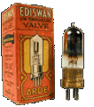
Another decade and the scene shifts to America. In late 1932 American
valve manufactures announced the first of a range of class B output
triodes, intended to provide high efficiency output stages. Several,
including types 19, 79 and 53 were twin triodes, but three, types 46, 49
and 52 were triodes with two grids. These were not tetrodes and were not
listed as such. Instead, with the two grids connected together they were
zero bias high mu triodes. In the other mode the outer grid was
connected to the anode, creating a low impedance, low mu driver for the
output stage. For battery receivers, the idea was to use a trio of 49’s
as a substantial output stage. However, they did not catch on. In
Rider’s Manuals of 1933 to 1935, I can find only 2 receivers, an Allied
and a Dewald, using 49’s in their output stages and both with a type 30
driver. Crossover distortion meant that Class B amplifiers were not
especially successful in domestic receivers anyway and the double triode
type 19 cost the same as a single 49 and effectively did the same job.
Popular Mechanics
But for an odd event, the 49 should have quietly disappeared into
oblivion as a valve for which there was little demand. However, someone
must have realized that the construction of the 49 made it a bi-grid and
experimented with it as a space charge valve. The outcome was that
around 1936, the “Popular Mechanics” magazine published details of an
odd little one valve regenerative receiver that required only 6 volts
high tension. It used – yes – a 49 in space charge mode, a coil and
solid dielectric tuning capacitor, two mica capacitors, a resistor and a
volume control “pot”, and not much else. Four penlight (AA) cells
provided the “H.T.”, with two torch cells to light the valve. The 6”
square baseboard had no panel. The suggested use was as a compact
receiver to fit into a hiker’s backpack.
Ever on the lookout for kitset material, the Lamphouse discovered the
“Popular Mechanics” article, saw its economic potential, and published
it without acknowledgement in their 1937 Annual. The rest, is as they
say, history. Here was a simple receiver with affordable battery
requirements and it became quite popular, especially with the youngsters
who could graduate up from a crystal set. Receiving aerials with 40ft
poles on Ľ acre sections were as ubiquitous as TV aerials are today, and
quite respectable DX with a Hiker’s was possible. Sydney’s 2FC was
commonly logged.
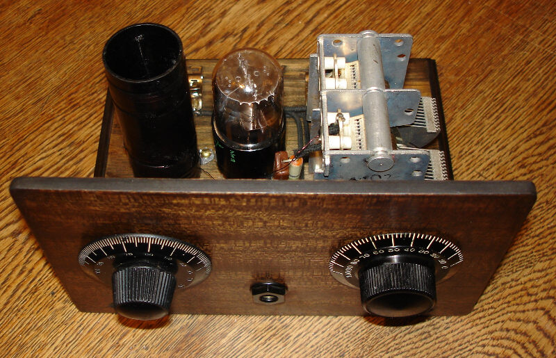
 The Classic Hiker’s The Classic Hiker’s
The Lamphouse experimented with the original and for 1938 came up with
the Improved “Hiker’s One”. In this, the “classic” version, there were
some important changes. The space charge grid voltage was reduced from
6.0 to 1.5 volts, and the H.T. was supplied by a 9.0 volt bias battery.
Conveniently, these were built up from 6 AA cells and fitted with
several Fahnestock clips which could be useful when building future
Hiker’s! The filament supply was now a No 6 cell, the standard for
manual telephones and with much greater capacity than a torch cell. Of
course, a single cell provided only 1.5 volts for the filament of the
49, but there was sufficient emission for the small anode and grid
currents of the Hiker’s without a significant reduction in performance.
Thrifty lads, myself included, chatted up the Post Office technicians
when they tested the batteries in the family telephone. The “worn out”
cells could be given a new lease on life if they had a few holes punched
in their sides and were stood in a preserving jar of salt water.
With the new improved version, the Hiker’s can be said to have arrived.
In one year, the Lamphouse claimed to have sold 4000 Hikers sets. This
figure did not take into account the large numbers, like mine, that were
built from parts from old receivers. (I blush now to admit that my first
Hiker’s used the tuning capacitor, coil and knob from an Atwater Kent
20c, but remember that in 1941, the obsolete 3 knob TRF receivers were
only about 15 years old and nobody wanted them.)
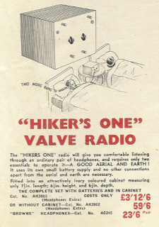
The Lamphouse would for an extra 9/6d (95cents) supply a ready assembled
Hiker’s and for 51/- ($5.10) you could have one complete with valve and
batteries, but no headphones, ready assembled in a little plywood case.
Several other firms, including at least one in Auckland, also sold
assembled Hiker’s in plywood boxes.
With the Hiker’s established as a steady seller, the Lamphouse cast
about for more business. A shortwave variant with plug in coil and the
regeneration control in the space charge grid supply soon evolved. The
Hiker’s, like all one valve receivers, could benefit from a bit more
audio level and so the companion “Hiker’s 49 Amplifier”, comprising a
3:1 audio coupling transformer and valve with socket on a baseboard,
appeared in the 1939 Annual. Rather than space charge operation, the 49
was connected in the low mu triode mode initially with 15 volts H.T. The
49 had an amplification factor of only 4.7 but with the transformer
provided a useful lift in the signal. An obvious move was to combine the
detector and amplifier on one baseboard, and shortly instructions for
building the Hiker’s Two with plug in coil on a small chassis were
published.
Scarcities
By the early 1940’s, New Zealand was very much at war and 49’s became
hard to find, and it seems likely that New Zealand had been the only
real market for them. Other 5 pin output valves such as 1F4 and 1D4
were tried in the Hiker’s with little success because they were pentodes
and the suppresser grid allowed littlespace charge action. The Lamphouse
recommended as alternatives, the 1A5, 1C5 and 1Q5 1.5volt filament
output valves which had by now become available. For Hiker’s sold by the
Lamphouse, the 49 became but a memory but now with an octal valve in
pentode mode the little set continued to be in demand.
The last year that the Lamphouse advertised a Hiker’s kit was 1951. For
1952, there was the “Lamphouse One” using a commercially made iron cored
coil. There was no primary winding, with the aerial connected to the
tuned winding via a 50pf capacitor.
For the experimenter, it was now a very different world from 1937. There
was more money about, and the war surplus market was thriving. Older
readers will remember Petone’s Sinewave George and his like who sold
lots of useful parts at bargain prices and made inroads into the normal
retail parts market. After 15 years the Hiker’s had had its day but it
is remembered as a unique little receiver that must have been
responsible for many young fellows taking a lifelong interest in radio.
by Peter Lankshear, Dunedin, New Zealand
|
 Main
Menu[
Home |
©redits
|
Search
| Promote
|
Links
|
Guest
Book |
What's New?
]
Main
Menu[
Home |
©redits
|
Search
| Promote
|
Links
|
Guest
Book |
What's New?
]