"The all seeing magic tuning eye will return you home"your tuned to 'boatanchors
downunder' radio
on 3402 Megs..
. A collaborative effort from collective sources resulting in 3.4GB
of data (2,000+ pages)ONLINE

Main Menu Home | ©redits | Search  | Promote  | Links | Guest Book  | What's New?  ]
Photo Albums
[  BoatAnchorsXtalSets | Detectors | Tubes & Boxes | Batts | Bakelites | Consoles | Trannies | Adverts | Service Vans  ]
Educational
Safety  | Basics  | Transformers  | Speakers  | Coils IF & RF | Caps Resistors & Pots | Valves 
Reference
[  Manuals | Terminology  | Capacitor | Resistor  | Diode  | Inductor  | Lamps  | Wiring  | Tubes: CV,VT,EU | Spectrum  ]
Projects
& Resources Plans  | Downloads  | Crystal Sets  | Tube TRF's  | Cyclops  | Hikers  ] *
Company's
[  Eddystone  | Collins  | Hammarlund  | Hallicrafters  | Marconi  | National  | RCA  | RME  ]
For Sale[  Books, New & Used  | Receivers | Test Equip  | Kitsets  | Tubes  | Misc & Hardware | Specials  ]
My Collection
| Services  |   | BoatAnchors  | Regens  | XtalSets |  | Literature | Tips  ]

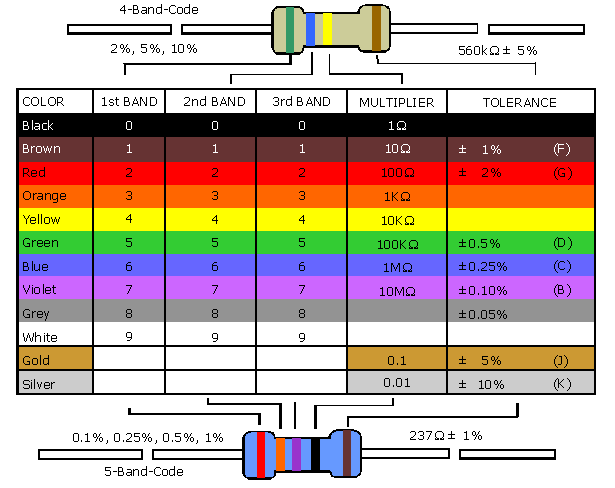
Resistor Colour Codes Table

   
Radio & Electronics Glossary
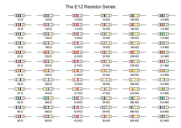
Resistor Colour Codes
Capacitor Colour Codes
Inductor Colour Codes
Wiring Loom Colours
 
Signal Diode Color Codes
Typical Radio Dial Pilot Lamps
VT Tube (Valve) Equivalents
CV Tube (Valve) Equivalents #2
ECU (foreign) to American Cross Reference
New Zealand Radio Spectrum
Get template to label your resistor drawers!
Great old resistor and capacitor chart (huge) to print for your wall

Molded Fixed Resistors  

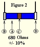
Figures 1 and 2

(1) the first figure of the resistance value in ohms is indicated by the body color (A) of the resistor.

(2) the second figure is indicated by the color of one end (B) of the resistor.


(3) the number of zeros following the second figure is indicated by the color of a dot (C) --Figure 1, or a band (C) ---Figure 2, at the center of the resistor. When no center dot or band exists, it is to be assumed that the dot, or band is of the same color as the body and the number of zeros is judged from that color.

(4) The percent of tolerance of the resistance value is indicated by another colored band (D) (either gold or silver) at the other end of the resistor. In the absence of the tolerance band, the tolerance value is assumed to be +/- 20%.

Resistor and Flexible Resistor Color Codes

A First
Figure
B Second
Figure
C Number
of Zeros
D
Tolerance
  0   0   0    
  1   1   1   1%
  2   2   2   2%
  3   3   3   3%
  4   4   4   4%
  5   5   5   5%
  6   6   6   6%
  7   7   7   7%
  8   8   8   8%
  9   9   9   9%
              5%
              10%
            None 20%
 
Heres some lables for you resistor drawers, click for larger image you can cut out


 2025 Copyrights | oldradios.co.nz