How To Series: About -
Speakers
|
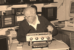
Peter Lankshear, Invercargill, New Zealand. photos coming soon...
[
Safety
|
Basics
|
Transformers
|
Speakers
|
Coils IF & RF
|
Capacitors
|
Resistors
& Pots |
Valves
]
 Speakers - The remaining iron cored low
frequency components encountered are the loudspeaker and, in some
instances, filter chokes. Chokes, although standard in the early mains
operated receivers, were not often used after the early 1930’s. There
was a period around 1950 when some locally made sets used them in
conjunction with permanent magnet speakers. Much like output
transformers in size and construction, chokes are normally trouble free,
and in an emergency, an output transformer can often make a workable
substitute if the secondary winding is ignored.
Speakers - The remaining iron cored low
frequency components encountered are the loudspeaker and, in some
instances, filter chokes. Chokes, although standard in the early mains
operated receivers, were not often used after the early 1930’s. There
was a period around 1950 when some locally made sets used them in
conjunction with permanent magnet speakers. Much like output
transformers in size and construction, chokes are normally trouble free,
and in an emergency, an output transformer can often make a workable
substitute if the secondary winding is ignored.
The Philips organization used permanent magnet speakers from the
earliest times. By 1933 they were using high efficiency magnetic alloys,
a decade before the United States. American receivers likely to be
encountered here, and Australian receivers made before the early 1950’s
used electromagnetic speaker fields. E.M. fields have a large inductance
and therefore make very effective filter chokes, provided that a bucking
winding of a few turns of heavy wire is connected in series with the
voice coil. This counteracts the hum induced in the voice coil by the
ripple in the field current. Care must be taken to connect the bucking
winding round the correct way. Wrong phasing adds a hum component
instead of canceling.
Field windings vary considerably in resistance, typically between 1000
and 2500 ohms, and windings are generally jumble wound rather than paper
interleaved. This is fortunate because one common cause of failure,
electrolysis, is minimized, although the cardboard formers can sometimes
cause corrosion. It is sometimes possible to repair an open field by
carefully peeling back the cardboard and looking for the telltale
greenspot. With patience, it is often possible to rewind a field coil.
One way is to fit the bobbin over a mandrel held in the chuck of a hand
drill clamped in a vice. Loudspeakers have a high casualty rate and
consequently, substitutes are often encountered. Depending on the desire
for authenticity, this in itself can be a problem, but more serious can
be the effect of a substitute if the field resistance is different from
the original. In the article on power transformers, the relationship
between H.T. voltages and field resistances was covered. Not only will
the incorrect resistance result in wrong H.T. voltages but also the
output tube can be at risk. Many designers used the voltage drop
developed across the field for supplying the bias voltage to the output
valve. Hence a lower resistance than normal will under bias the output
tube, shortening its life and creating possible overheating, whilst over
biasing can cripple the output power and create high distortion.
Loudspeakers are subject to faults associated with the rather fragile
cone and suspension. Careless fingers, mice, moisture and excessive
volume can all produce tears and holes. Careful gluing and patching can
frequently restore a cone but flexible cement such as carpet glue or a
contact adhesive is essential. Fuzzy sounds result from the voice coil
rubbing on the pole pieces, dirt in the gap or sometimes loose voice
coil turns. The older speakers can be repaired but modern ones,
particularly permanent magnet types, are just about unrepairable. The
key item is the voice coil centering device, aptly called in the early
speakers, the ‘spider’. If the problem is centering, front spider units
are the easiest to deal with. The procedure is to loosen the locking
screw, insert three narrow strips of photographic film equally spaced as
shims in the gap between the centre pole and the voice coil, and
retighten the screw. Speakers with spiders behind the cone are dealt
with in much the same way but sometimes there is a disc of felt attached
to the centre of the cone to exclude dust. This has to be removed first.
Occasionally the centre pole will be out of centre in the gap. This
problem, and voice coil faults, requires first that the cone be removed.
If the cone surround is bolted on, as for example in Atwater Kent
speakers, you have it made. More likely though, it will be firmly glued
on and considerable care will have to be taken not to cause damage. When
the cone is successfully removed, the gap can be adjusted by loosening
the assembly bolts, inserting three nails or drills of suitable diameter
as spacers between the poles, and the bolts retightened. If the voice
coil has loose turns, a thin coating of polyurethane lacquer should do
the trick. From all of this, it is apparent that the newer speakers,
with welded construction and corrugated disc spiders are just about
unrepairable.
A major problem for the restorer striving after authenticity is the
absence of the correct replacement. A huge range of speakers has
appeared during the history of radio. Whilst there were numerous
specialist manufacturers of speakers, such as Rola, Magnavox, Celestion
and Utah, many major receiver makers had their own patterns and
experienced collectors can frequently identify them at a glance. Indeed,
there is scope for an extensive and unique collection just of radio
loudspeakers, even without the multitude of “Hi Fi” speakers that have
been marketed.
Sometimes, there is no option but to use a substitute. If a speaker with
similar characteristics can be obtained, there is not much of a problem.
Significantly different field resistances should be avoided. It is
likely that a variation of up to 500 ohms will not create any
difficulties, provided any field-derived bias is compensated for.
However, a resistance of 1000 ohms or so greater than the original would
not be advisable without adjustment of screen and oscillator voltages.
To avoid excessive H.T. voltages, a low resistance field can be ‘[padded
out’ by the use of a series connected 10 watt resistor of the correct
value. If this course is adopted, it is a good idea to add an extra
10mfd. Filter capacitor at the junction of the field and resistor. This
will counteract any hum caused by the lower inductance of the smaller
resistance field.
As few E.M. speakers have been made during the last 35 years, inevitably
there will be occasions when permanent magnet replacements are the only
option. The problem then is how to substitute for the field. Sometimes
the magnet assembly will have been removed from the original speaker and
attached to the cabinet somewhere. Whilst this is a practical servicing
solution, it is unlikely to satisfy the critical collector. Of course,
anything less than E.M. speaker will not please the purist, but there
are a couple of reasonable compromises. First choice would be to use a
filter choke and a series ‘building out’ resistor. For example, if the
original field resistance was 1500 ohms, and the selected choke has a
resistance of 400 ohms, a 10 watt 1000-1200 ohms series resistor would
be suitable. Care must be taken to mount the resistor where it will be
well ventilated and away from fingers and other components. The choke
should not be mounted near the speaker transformer or close to valves.
Failure to observe this may result in induced hum.
The simplest and most popular way round the problem is to use a couple
of resistors in series as a substitute for the field, with an additional
filter capacitor connected to the junction of the resistors. This is the
method adopted by many manufacturers, but because resistors are in no
way as effective as chokes and fields, a considerable increase in filter
capacity will be needed. The use of large capacitors has traps for the
unwary and their use will be covered in a later article.
 |
|
 Main
Menu[
Home |
©redits
|
Search
| Promote
|
Links
|
Guest
Book |
What's New?
]
Main
Menu[
Home |
©redits
|
Search
| Promote
|
Links
|
Guest
Book |
What's New?
]