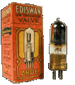
How To Series: About - Valves
(Tubes) a.k.a bottles, jars
|
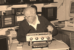
Peter Lankshear, Invercargill, New Zealand. photos coming soon...
[
Safety
|
Basics
|
Transformers
|
Speakers
|
Coils IF & RF
|
Capacitors
|
Resistors
& Pots |
Valves
]
related links:
CV Numbers,
VT Tube Equivs, American to Foreign, Obsolete Rare QRG's
 Valves - There is a widespread public
misconception that valves are extinct and unprocurable. I suspect that
this myth was fostered by some sections of the electronics retailing
industry as part of the planned obsolescence philosophy and a ready
excuse for avoiding uneconomic servicing work. Receiving valve
production has long ceased, but vast inventories have survived and there
will be no critical shortage of post 1936 types in the foreseeable
future. Some earlier varieties are scarce. Pre 1930 American battery
valves are in demand, but there are firms still selling them. Most
difficult to find locally are the pre 1935 English and European types.
They were never imported into New Zealand in any large numbers and
wartime destruction and depletion left few stocks in Europe. Even so, it
is possible, with a bit of perseverance, to locate many spares. American
and most of the post war European types are readily available from the
Antique Electronic Supplies whose address is at the end of the series.
Valves - There is a widespread public
misconception that valves are extinct and unprocurable. I suspect that
this myth was fostered by some sections of the electronics retailing
industry as part of the planned obsolescence philosophy and a ready
excuse for avoiding uneconomic servicing work. Receiving valve
production has long ceased, but vast inventories have survived and there
will be no critical shortage of post 1936 types in the foreseeable
future. Some earlier varieties are scarce. Pre 1930 American battery
valves are in demand, but there are firms still selling them. Most
difficult to find locally are the pre 1935 English and European types.
They were never imported into New Zealand in any large numbers and
wartime destruction and depletion left few stocks in Europe. Even so, it
is possible, with a bit of perseverance, to locate many spares. American
and most of the post war European types are readily available from the
Antique Electronic Supplies whose address is at the end of the series.
As these servicing notes have an emphasis on post 1935 receivers, valve
supplies concerned are not likely to be a major problem. A most common
type encountered in this group is likely to be the octal series. This is
fortunate, because the octals were produced internationally, and large
quantities of war surplus stocks were released at bargain prices. Later,
the all glass miniatures were, with the exception of the Rimlocks, also
produced internationally and supplies are still good. Similarly Loktals
are not a real problem. One unexpected development has been the
resurgence of valve technology in the HiFi and musical industries, whose
enthusiasts insist that the only sounds suitable for their golden ears
are generated by big valves and transmitted along gold plated cables
made from oxygen free copper. The outcome has been continuing
manufacture of major audio amplifier valves in “Eastern Bloc” countries.
The first problem is ascertaining whether or not a valve is useable.
Although common only with battery valves, the easiest fault to locate is
an open filament. Absence of any light and a quick test with an ohmmeter
will give the answer. A related fault can be puzzling. The filament has
continuity and the envelope gets warm after a few minutes, but there is
no glow from the filament. The problem is that some air has leaked into
the valve.
Most common and readily understood is wearing out or more correctly,
loss of emission. To judge just at what stage a valve becomes
unsatisfactory requires experience and an understanding of what a valve
is doing in its particular application. To give an extreme example-,
some- receivers used a general-purpose triode as a detector by earthing
the anode and using the grid as a diode. Even with a very strong signal,
the cathode was only supplying a few microamperes, well within the
capabilities of the most worn out valve. Conversely he same type of
valve may have been used as the heterodyne oscillator in a shortwave
receiver, where a low emission specimen would not work at all well. Even
brand new valves vary considerably from their published performance
figures, some parameters having a tolerance of plus or minus 20%. Thus
the mutual conductance of a new 6K7 may be as low as1.15 ma/v or as high
as 1.74 ma/v and yet the still be within specification.
Valves can suffer from many faults. Open filaments are common in
directly heated types and leave no doubt as to the valve's worth. Less
obvious is leakage- or a short circuit between elements. Sometimes these
can be picked up with a resistance check between pins, but
unfortunately, these faults may not occur until the valve is hot.
Particularly serious is short-circuiting between heater and cathode in
some indirectly heated rectifiers, such as 84, 6X4, 6X5, and the EZ--
series. It was common practice in cheaper receivers to use a common,
earthed filament winding on the transformer. A contact between the
rectifier heater and cathode will, in this system, result in the
full-rectified H. T. being short-circuited to ground. This can destroy a
power transformer in a few moments, so be very alert to this problem and
switch off promptly if the rectifier shows any signs of distress.
Few beginners are likely to own a valve tester, but this is not
necessarily a major problem, as probably more valves have been
incorrectly diagnosed as faulty by inadequate interpretation of valve
tester readings than for any other reason. Many testers check little
more than cathode emission and for short-circuited elements. With their
BAD-?-GOOD scales, they may have impressed the customer, but did not
necessarily tell the full story. Still, don’t pass up the opportunity of
acquiring one if you get the chance, these checkers do provide some
useful information. The major testers such as the Weston, Taylor,
Precision and AVO, which test mutual conductance as well as emission
characteristics are really necessary for a comprehensive assessment, but
they do require a good knowledge of valve parameters to produce the best
results. Valve testers, and test instruments generally are like the
doctor’s stethoscope. By itself it won’t tell you anything that makes
sense, but requires processing between the operator’s ears.
It is most important that if you have the chance of buying a valve
tester, make sure that its manual of test figures is available.
Regardless of what tester, if any is used, the ultimate assessment is
whether or not a valve works properly in a receiver that is known to be
performing well. This presupposes of course that the test receiver uses
the same type of valve, or its equivalent. Tune the receiver to a weak
station, and compare the performance with the original valve. If the
sensitivity and hiss are similar, there is a fair chance that the valve
is OK In the case of converter valves, check that there are no dead
spots, indicating low oscillator performance. Confirm at high volume
that output valves can deliver full output without distortion. Tapping
the valve with the handle of a small screwdriver should check
intermittent mechanical faults'. There should be no crashing or banging
noises, indicating loose welds. Note that directly heated filament
valves are likely to be microphonic. This is normal. Push the valve
around to in its socket to check for intermittent operation. This may
result from base pin soldering problems and will be covered later. Be
alert though for. Faulty sockets in receivers creating confusing contact
problems of their own.
Rectifier condition can best be checked under operating conditions by
comparing the HT voltage with the service data or t hat produced by a
known good valve. Sometimes the two sections of a rectifier will become
unbalanced. This is not of any great consequence if the HT is
satisfactory, but, with one side more efficient it is possible for the
ripple to have a 50Hz component which may not be filtered as well as the
normal 100Hz hum. If the voltage is reasonable and hum level
satisfactory, keep it in service.
VALVES (tubes) continued
Apart from bent pins, which can be carefully straightened, the glass
based valves have few physical problems that can be corrected. However,
the older valves are prone to a number of faults in soldering and
cementing which are repairable. Today, there is a large range of
adhesives for all purposes, including those that adhere strongly to
glass. Considering that in the heyday of valve manufacture there was
nothing of this nature available, remarkable results were achieved with
glues inherited from lamp making, some as simple as a mixture of resin
and plaster of Paris for fastening bases and grid caps. Now, 70 or more
years later, these cements are losing their grip and due care should be
taken. The most difficult time for a valve is during extraction from a
socket, so ease bases gently out of sockets. One way is to use a
screwdriver as a lever under the base, and grid clips should be loosened
in a similar way.
If a grid cap is loose, but the wire is intact, simply unsolder the top
of the cap and after carefully straightening the wire, take the cap
right off the valve. With a. knife, scrape off any adhesive adhering to
the glass. Make sure that the wire is well tinned. Now clean out the cap
and glue it back on to the valve with a two pack Epoxy resin, superior
in my opinion to instant "Power Glue" which is not gap filling and
relies on intimate contact between mating surfaces. Wait a day until the
glue has hardened before resoldering the lead. Excess adhesive can be
removed with a sharp knife a couple of hours after gluing.
Inserting some adhesive between the glass and the base can often
refasten loose bases. In this case, if the original cement has not
crumbled, power glue may be satisfactory. The most serious results of
base loosening occur with valves with metallized coatings such as the
gold and red Philips series and grey zinc. At the junction of the base
and the glass is a fine earthing wire, which also loosens when the
cement bond is broken, resulting in instability and noises. The most
practical repair is to first re-glue the base, and then, after cleaning
some of the paint off the earthing wire, tightly and evenly wind on
about a dozen turns of 5 amp. fuse wire immediately above the base.
Carefully solder the earthing lead to the fuse wire and smear some epoxy
resin over the winding. The result is likely to be a bit unattractive,
but can be disguised by wrapping a narrow strip of tape or paper around
the top of the base.
One of the best features of the all glass valves was the elimination of
soldering to the base pins and grid caps. In the older separate base
construction, only the tips of the lead out wires and the base pins are
soldered. The bond is easily broken when the base loosens, and creates
an intermittent contact, often triggered by pushing the valve around in
its socket. This is the cause of a particularly annoying fault in which
the heater will start to cool, causing a the receiver to fade over a
period of 5-10 seconds, and even happens in valves with well cemented
bases. Resoldering is sometimes successful, but not always, because
often, the wires are black with oxides and probing around in an attempt
to clean the surfaces is unsuccessful. Then the only remedy is to remove
the base and clean the leads properly. This may seem to be a daunting
process, but with a bit of patience, it is really quite straight
forward. It is not a bad idea to practice on a discarded valve first!
Start by working the base a few degrees each way and it will soon loosen
up. Then melt the solder out of the pins and carefully pull the base
straight off so as to retain the lead configuration. The wires will be
seen to emerge from the press at the top of the stem and a bit of quiet
study will show that they follow a sequence with the filament leads at
the middle of the press, and finishing with the anode at one side. Draw
a diagram of the leads and their pins. Carefully clean the bottom of
each lead with fine sandpaper and coat it with solder. It would be nice
to be able to resolder the leads directly to the pins, but invariably
they first need extending and again, 5 amp fuse wire is suitable. Wrap
the fuse wire around the leads so that they will enter their pins
without catching and solder them. Now make sure that there will be no
contacts between leads. Sometimes manufacturers will have used sleeving
if there was a chance of a short circuit and if necessary you can do the
same. Thread the leads back into their pins and after applying adhesive
to the inside of the base, carefully position it back on to the bulb.
Resolder the pin tips, trim off the surplus wire and the job is done.
This technique can be used on odd occasions when a valve base is
damaged, but the internals are thought to be OK A typical case is when a
rectifier base arcs across and carbonizes a track. Putting on a new base
will often save an otherwise unserviceable valve. There may also be
times when an original type is hard to find, but a later equivalent is
common. A typical example is the 6D6 and the 6U7G. Modifying a valve
with a new base and grid cap is far less drastic than the alternative of
attacking a chassis to change to a different type of socket.
Defective soldering to a grid cap is common and can cause frustrating
symptoms similar to those caused by a faulty capacitor. The receiver
seems a bit insensitive and a sudden noise impulse such as from an
appliance switching will cause the sensitivity to return to normal.
Unsoldering the cap will often reveal a completely un-tinned and black
lead that should be scraped clean and resoldered
Frequently, a grid lead will break off flush with the surface of the
glass and at first sight, the valve appears to be a write off. With a
bit of care, it is possible in about 90% of cases to resurrect the
valve. Most grid lead seals have a fair depth of glass, and can spare up
to a half a millimeter. With a sharp, very fine triangular file make
three or four cuts in the glass at the tip of the seal. On the fourth
cut, the glass tip is likely to break off, leaving a short piece of wire
exposed, hopefully with the internal vacuum intact. Now take a piece of
the ubiquitous fuse wire and make a small loop in the middle. Lasso the
projecting tip of grid wire with the loop, and carefully apply some
solder. Twist the two tails of fuse wire together to become the new grid
lead.
VALVES (tubes) continued
Fortunately, valves are available for the majority of receivers, but
there are occasions when an exact replacement takes some locating. At
this stage the question of equivalents versus alternatives arises. For
example, several Columbus models introduced in 1940 were supplied with
Marconi/Osram DH63 detector/1st audio valves. The DH63 is identical to a
6Q7G, and only a perfectionist would be concerned about using the more
readily available latter type as a replacement. However, it is quite
likely that in fact a lower gain alternative Philips EBC33 will have
long since been installed. This was a common practice, due to
restrictions of US dollar imports in the 1950’s. Similarly it is common
to find EF39 and ECH35 as substitutes for the American pentodes and
converters. There is little practical difference in performances.
It was only during the last decade or so of valve development that
numbering and interchangeability became internationally universal. Even
then, Europe and America retained their own traditional naming systems,
but they did at least make direct equivalents. Thus Europeans made the
American 6BA6 and called it the EF93, while the Americans copied the
EL84 and called it the 6BQ5, but most importantly, both names appeared
on the packets.
Prior to 1950, only the American Radio Manufacturers Association valves
had anything like worldwide acceptance. The Philips system was the
nearest that Europe had to a standard. Many of the smaller makers had
their own naming systems, and even experienced technicians can get into
difficulties when trying to find replacements for some of the lesser
known British or European valves. Lists of equivalents are published but
they are not always complete or absolutely reliable. These lists were
often compiled by valve manufacturers who naturally encouraged the use
of their own product, even if it involved a socket change. Old timers
will remember the series of BRIMAR advertisements about substituting
valves. The catch phrase was "Be Wise -Brimarise". Actually, socket
changing should be a last desperate resort. Better to modify a
substitute valve with a base of the required type, or make up a plug in
adaptor from a valve socket and base. The exact type of valve may turn
up later. Obviously, it would be impossible to cover every type of valve
likely to be encountered, but I will deal with some of the main groups
and some of, which may have particular problems.
Easiest range to deal with is the pre-octal American 6.3 volt series.
With a few exceptions, each type was unique, and without a direct
replacement or European equivalent. There are two well known
interchangeable pairs though, the 77 = 6C6 and the 78 = 6D6, which,
although physically different have only minor electrical differences.
The main thing to watch for is that the 6C6 and 6D6 require better
shielding than the others. In the majority of cases, types 41 and 42 can
be interchanged, but the 42 has nearly double the heater current of the
41. Frequently, a 37 triode can be replaced by a type 76.
The American 2.5 volt A.C. heated valves can be divided into two
categories. The early group comprised the 27, 224 or 24A, 35 or 51, and
the 45, 46 and 47. Philips produced the early 2.5 volt series using
their own numbering system, but these valves are rare:- F203 = 45. F209
= 27. F215 is similar to 56. F242 = 24A.
A type 56 will often be found substituting for a 27. There is no direct
equivalent for the 35/51. A pair of type 45 output triodes might be
replaced by a pair of 2A3's BUT an extra 2 amperes would be required by
the, filaments -too much for many transformers. Several of the later 2.5
volt series had 6.3 volt equivalents and this resulted 'in a servicing
ploy whereby a 2.5/6.3 volt transformer was connected to the sockets
involved, and the more readily available
6.3 volt valves substituted. For example, it is common to find a 42 in
place of a 2A5. Be on the look out for this trick because the sockets
may have their original labeling, and plugging in a 2.5 volt valve could
well result in a burnt out heater.
Very collectable radios from the 1930's were made in the U.S.A. by
Majestic, and in Canada by Rogers. These were unique in North America in
that they used valves equivalent to the RMA standard, but which were
zinc spray shielded. Some had an extra base pin to earth the shielding,
but many had standard bases with the screen connected to the cathode or
were earthed via a chassis mounted contact finger. Replacements can be
hard to find, and the standard versions may have to be used. Other
manufacturers who made replacements, overcame the shielding problem by
supplying the valves fitted with "Goat" shields, made of two pieces of
tinplate contoured to fit like a suit of armour and held in position
with a wire circlip. Goat shields were quite common and can still be
found.
The Octal series was so prolific that I doubt if any collector would
have difficulty in finding correct replacements. British Marconi Osram
had their own numbering system. A few types were peculiar to M/O, but
most were identical to standard American valves. Some European
manufacturers, including Philips, made alternative octals. Their
characteristics were different from the American series, although in
many cases they could be used as plug in replacements. These valves were
used extensively in N.Z. made receivers. Philips unwittingly created
problems for collectors. During the 1950's, as already mentioned their
Red Octal Series valves frequently replaced the RMA series, but they
were of course, shielded. As a result many sets are now minus some valve
shields!
Loctal valves were made in Europe as well as the U.S.A. and apart from
the ECH21 and EBL21, most of the common types have equivalents in both
systems. Replacements can generally found without trouble. Rimlocks were
only made by European manufacturers and may be the first of the post war
valves to become scarce.
The real problems occur with the pre 1940 English and European valves.
Most of the large number of makers had individual numbering systems, and
some types with different bases had the same names. As an example, here
is a list of some equivalents for a common type of valve, a 4, volt
heater double diode / medium mu triode:-
Mullard...TDD4, Philips...ABCl, Triotron..DT436, Ever-Ready ….A23A,
Marconi/Osram HD4 or DH42, Ekco. DT41, Tungsram..DDT4, Hivac.. AC/DDT,
Mazda ..AC/HLDD. These are all interchangeable!
Clearly. finding replacement valves of this period entails a fair bit of
research and luck. I strongly recommend obtaining lists of equivalents
and above all, valve characteristic tables. Learn what the various valve
parameters mean, because you can then work out your own substitutes.
 |
|
 Main
Menu[
Home |
©redits
|
Search
| Promote
|
Links
|
Guest
Book |
What's New?
]
Main
Menu[
Home |
©redits
|
Search
| Promote
|
Links
|
Guest
Book |
What's New?
]